Prepare the Raspberry Pi Micro SD Card
If you have a headerless version, solder a header strip on the top (normal position) but it is probably just easier to buy one with a header already attached (WH model).
Download & install Raspberry Pi Imager & run, pick Raspberry Pi OS (Other) -> Raspberry Pi OS Lite (32-bit) and write to a Micro SD Card (recommend 4GB).
Once Imager has finished safely remove the Micro SD Card & re-insert. Ignore the Format warnings if on Windows and you should see a drive called boot
Now set-up the Raspberry Pi WiFi by creating a file in the root directory called:
wpa_supplicant.conf
In this file add the following (use notepad++), replacing YOUR... with yours:
						country=GB

						ctrl_interface=DIR=/var/run/wpa_supplicant GROUP=netdev

						update_config=1

						network={

						  ssid="YOURSSID"

						  scan_ssid=1

						  psk="YOURPASSWORD"

						  key_mgmt=WPA-PSK

						}
We also need to enable SSH by creating another file in the root directory called ssh. You can now safely remove the Micro SD Card.
Initial Set-up of Raspberry Pi Zero W
Put the Micro SD Card into the Pi and plug into a power source giving the Pi a few seconds to boot (green led will flash, wait for solid).
Open a Powershell window (or equivalent if not using windows) and type:
ssh pi@raspberrypi.local
You may get a message about fingerprint, just type yes.
If this isn't the first Pi you've used you may get a security warning and if this happens type the following to remove the previous version:
ssh-keygen -R raspberrypi.local
The default password is raspberry and if everything is ok you will now see the pi@raspberrypi prompt.
If you get a Connection timed out or similar message then check the Wi-Fi settings and try again. I'd recommend you now change your default password with passwd.
I'd also recommend you update and upgrade the Pi with the following commands (go make a brew as this can take a while):
sudo apt-get update
sudo apt-get upgrade
Now launch the config tool with sudo raspi-config and turn on the hardware Serial Port via:
- Option 3 Interface Options
- Option P6 Serial
- Login to be accessible over serial? No
- Would you like the serial port hardware to be enabled? Yes
Exit the config tool & reboot
Setting up the Pi for OqtaDrive
While the Pi is rebooting download the lastest OqtaDrive Software
You need the source code & the linux_arm files and once downloaded unzip & copy oqtactl (in the linux_arm zip) & oqtadrive.ino
(in the source zip arduino folder) to a safe place on your PC. Log back into the Pi after reboot with
ssh pi@raspberrypi.local
Make a directory for OqtaDrive using mkdir oqtactl. I'd recommend oqtactl as we will use oqtadrive later for the Arduino sketch.
Launch another Powershell (or equivalent), navigate to the safe place you've put oqtactl & oqtadrive files.
We will now use scp to copy the files across to the Pi (you can use other tools to do this). In the PC PowerShell type:
scp oqtactl pi@raspberrypi.local:oqtactl
On the Pi change to the oqtactl directory cd oqtactl and make the oqtactl executable with:
chmod +x oqtactl
Back on the PC copy over the Arduino file with
scp oqtadrive.ino pi@raspberrypi.local:oqtactl
Setting up the Pi to Flash the Nano
On the Pi type cd to get back to the home directory and install the arduino-cli with:
curl -fsSL https://raw.githubusercontent.com/arduino/arduino-cli/master/install.sh | sh
You will probably get the message arduino-cli not found. You might want to add /home/pi/bin to your $PATH
so to do this type:
nano ~/.bashrc and at the end of the file add export PATH=$PATH:/home/pi/bin
Either reboot the pi with sudo reboot or just type export PATH=$PATH:/home/pi/bin on your command line
for this to be picked up. Type arduino-cli to test and the help should show. Create a configuration file and a new sketch using:
arduino-cli config init
arduino-cli sketch new oqtadrive
Move oqtadrive.ino from the oqtactl folder to the oqtadrive folder (overwriting the default one the sketch created) using:
mv oqtactl/oqtadrive.ino oqtadrive
If you want edit the oqtadrive.ino file to change the config use:
nano oqtadrive/oqtadrive.ino I set #define LED_RW_IDLE_ON false
From the home directory (type cd) run the following to set everything up for flashing:
- Update the Arduino available platforms and libraries
arduino-cli core update-index
- Install the avr board support
arduino-cli core install arduino:avr
- Download dependencies and create folders
arduino-cli compile -b arduino:avr:nano -p /dev/serial0 -t oqtadrive/oqtadrive.ino -v
- Install some dependencies for the using the GPIO to reset the Nano
sudo apt-get install -y python3-dev python3-rpi.gpio minicom
As we are trying to program the Nano via the hardware serial and not the USB we need to make some changes as detailed on Siytek.
On the Pi navigate to the folder containing avrdude executable which after running all of the above should be in the folder (version numbers may differ):
cd /home/pi/.arduino15/packages/arduino/tools/avrdude/6.3.0-arduino17/bin
Move the avrdude executable to a backup using mv avrdude avrdude-original and then download some replacement scripts
which allow us to flash the Nano via the GPIO. *NOTE the old scripts have syntax issues with Python3 so replaced with fixed versions
on my website
curl https://tomdalby.com/other/files/autoreset -o autoreset and then chmod +x autoreset to make it executable.
curl https://tomdalby.com/other/files/avrdude -o avrdude and then chmod +x avrdude.
- **v1.0 PCB only
nano autoreset and change the line pin = 18 to pin = 24
nano avrdude and add the path to avrdude-original and |autoreset
This will give you an avrdude containing:
				#!/bin/sh


				sudo strace -o "|/home/pi/.arduino15/packages/arduino/tools/avrdude/6.3.0-arduino17/bin/autoreset" -eioctl /home/pi/.arduino15/packages/arduino/tools/avrdude/6.3.0-arduino17/bin/avrdude-original $@
and autoreset containing (v1.0 PCB version, v1.1 pin = 18):
				#!/usr/bin/python


				import RPi.GPIO as GPIO

				import sys, os, re, time, fcntl

				import errno


				fd = sys.stdin.fileno()

				fl = fcntl.fcntl(fd, fcntl.F_GETFL)

				fcntl.fcntl(fd, fcntl.F_SETFL, fl | os.O_NONBLOCK)


				GPIO.setwarnings(False)

				GPIO.setmode(GPIO.BCM)

				dtr = re.compile('.+TIOCM_DTR.+')

				start = time.time()

				pin = 24


				def reset():

				GPIO.setup(pin, GPIO.OUT)

				GPIO.output(pin, GPIO.HIGH)

				time.sleep(0.32)

				GPIO.output(pin, GPIO.LOW)


				def process():

				while True:

				try:

				duration = time.time() - start

				input = sys.stdin.readline().strip()

				if input is None: # == "":

				input = sys.stdin.readline().strip()

				if dtr.match(input):

				reset()

				return

				elif duration > 5000:

				return

				except Exception as e:

				if hasattr(e, 'errno'):

				if e.errno != 11: # Ignore resource unavailable

				raise

				else:

				raise


				process()

				print ("avrdude-original: Using autoreset DTR on GPIO Pin " +str(pin))

				GPIO.cleanup()

				exit
Shutdown the Pi with sudo shutdown now and wait for the Pi LED to go out.
Flash the Nano using the Pi
You can always flash the Nano using your PC and a USB cable but using the Pi allows you to do this wirelessly plus saves messing with the
PC Arduino sofware and associated drivers.
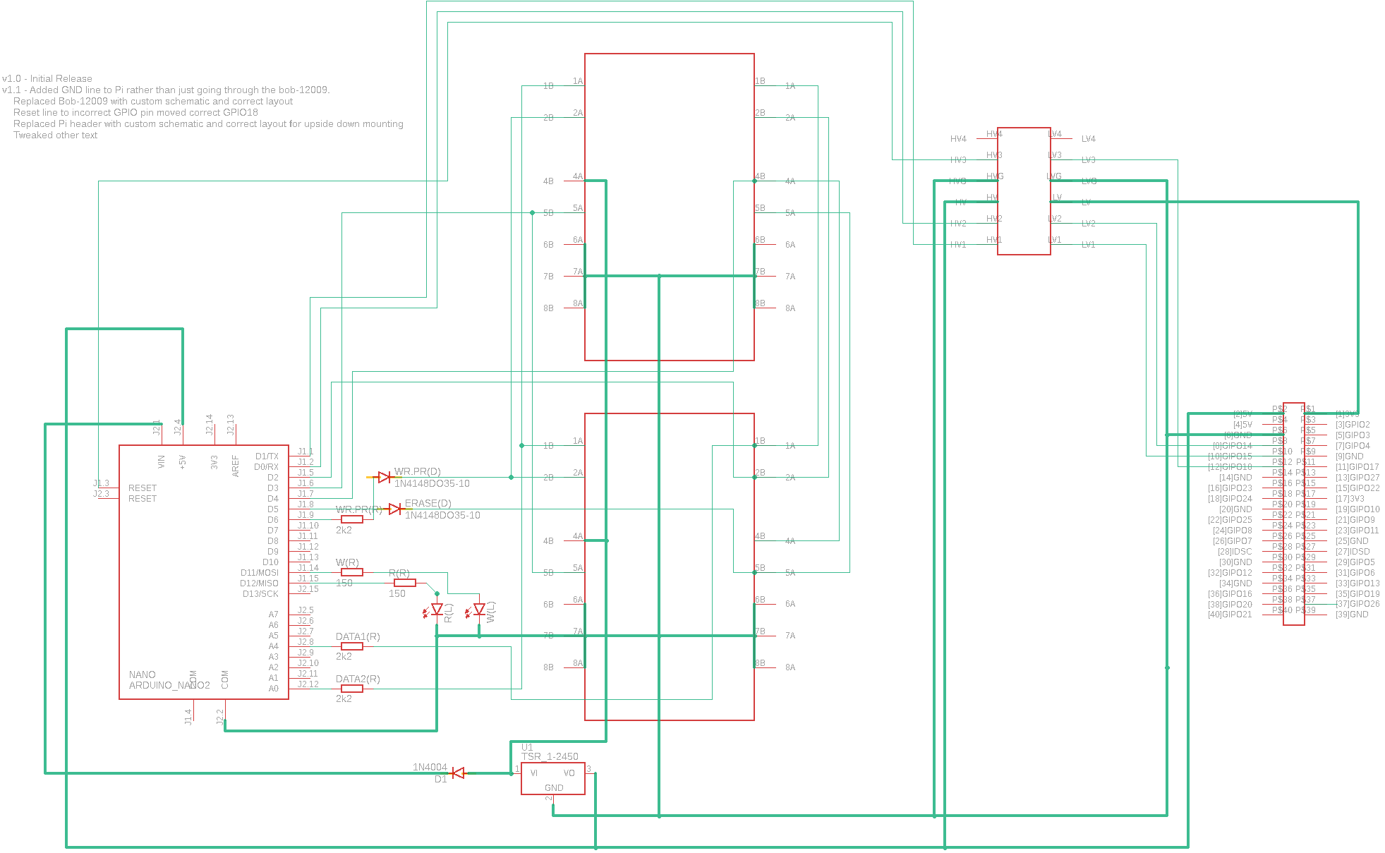
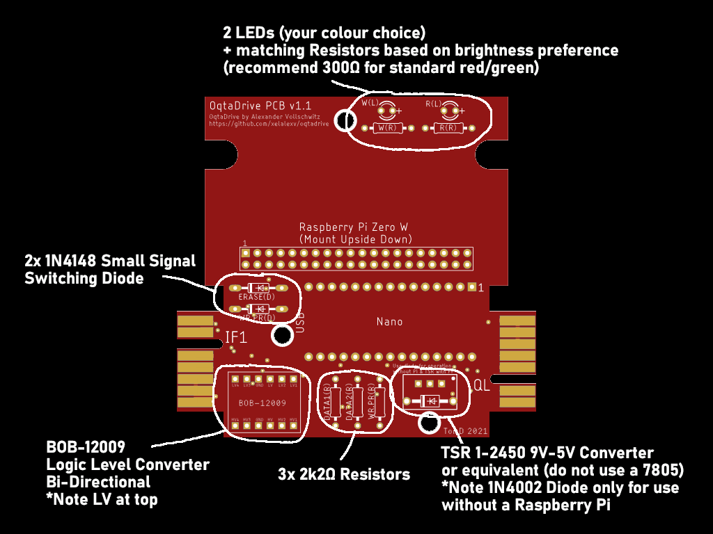
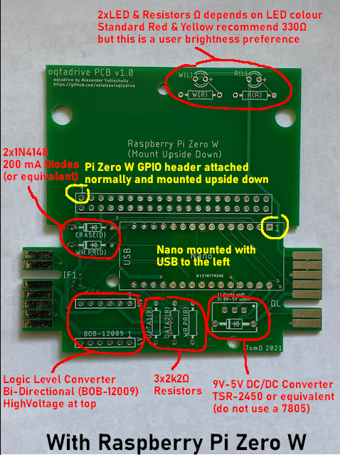
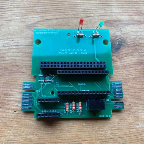
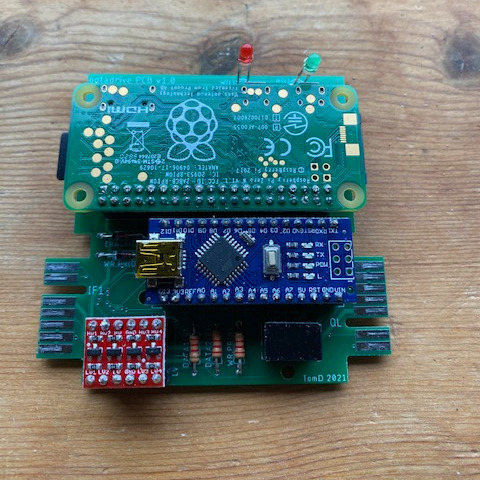
After constructing the PCB, connect everything up and then power on the board.
Probably the best way initially is via the USB on the Pi but for future flahes this could be by connecting it all up to the Specturm or QL.
Log back into the Pi after the reboot using ssh pi@raspberrypi.local and from the home directory run the following:
arduino-cli compile -b arduino:avr:nano -p /dev/serial0 -t oqtadrive/oqtadrive.ino -v to compile the sketch
- followed by
arduino-cli upload -b arduino:avr:nano -p /dev/serial0 -t oqtadrive/oqtadrive.ino -v to flash the Nano
- Depending on your nano board you may need to use
arduino:avr:nano:cpu=atmega328old instead (older models)
If all goes well the Nano will be flashed. If you get sync errors then try the alternate arduino board (above) plus try again after a reboot.
This is usually the step that has the most issues, as a troubleshoot make sure you did the chmod +x on the scripts and that you
have the correct reset pin in autoreset (24 for the v1.0 and 18 for the v1.1 PCB). Also run arduino-cli core update-index again just be sure.
Set-up the OqtaDrive daemon
Assuming you are still logged into the Pi (if not boot the Pi and log in), then type:
sudo nano /etc/systemd/system/oqtadrive.service and put the following in this file:
			[Unit]

			Description=OqtaDrive

			Requires=local-fs.target

			[Service]

			ExecStart=/home/pi/oqtactl/oqtactl serve -c if1 -d /dev/serial0

			WorkingDirectory=/home/pi/oqtactl

			StandardOutput=inherit

			StandardError=inherit

			Restart=always

			User=pi

			[Install]

			WantedBy=multi-user.target
/dev/serial0 is the hardware serial GPIO port and -c if1 initially boots the OqtaDrive in IF1 mode. Change this
to QL if this is your machine of choice (you can always resync later). Requires=local-fs.target means the filesystem should be loaded
before running this. Waiting for the filesystem means it takes around 30seconds to boot the OqtaDrive from power on.
You can get the daemon to boot quicker by replacing this with DefaultDependencies=false but be careful that this
has not been tested fully. To load and enable this new service type:
sudo systemctl daemon-reload and then
sudo systemctl enable oqtadrive.service to enable the service
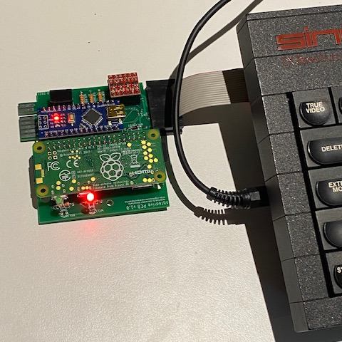
We are now ready to plug this OqtaDrive standalone into either the QL or Spectrum. Power down with sudo shutdown now.
Remove the USB cable and attach the Microdrive cable to the correct side for the computer. Power on the computer and if all is well
the LEDs will flash for around 30seconds and then will either go out (if you set #define LED_RW_IDLE_ON false) or be static.
Once this happens the OqtaDrive is ready to use.
Using the OqtaDrive
The OqtaDrive Git Hub site has examples of how to control the drive but as a quick
summary. Download the latest version of oqtactl for your PC. Put it in a directory with some Microdrive cartridges
(and .Z80 snapshots). You can then use some of the following commands from a PowerShell (or equivalent):
./oqtactl ls -a raspberrypi:8888 to list cartridges loaded
./oqtactl resync -c if1 -a raspberrypi:8888 to resync the drive for IF1
./oqtactl load -d 1 -i "WhereTimeStoodStill.mdr" -a raspberrypi:8888 to load a Cartridge
./oqtactl load -d 1 -i "Defenders of the Earth (1990)(Enigma Variations)(128K).z80" -a raspberrypi:8888 to load a Z80 snapshot
raspberrypi:8888 is the address of the Pi Zero W so if you've changed that you need to change this.
One final thing, before powering off your computer I'd recommend you shutdown the Pi first as it is safer.
The command ssh pi@raspberrypi.local "sudo shutdown now" does this. Wait for the LEDs to
flash and then you can power off. Soft resets don't need this (Spectrum+ models or QL) as this doesn't remove the 9V power into the OqtaDrive.
Running this unit on a 48k non-plus machine without a reset switch is therefore not great due to the 30sec wait each time you reboot so
I'd recommend putting in a reset switch for these models (across Capacitor C27).
(Optional) Remove un-needed components for faster boot and lower power draw
These don't really add anything as installing the Lite verison of the OS disables most things but I do them to save a few mA and mS.
sudo nano /boot/config.txt with the following changes:
			# Disable the rainbow splash screen

			disable_splash=1


			# Disable bluetooth

			dtoverlay=pi3-disable-bt


			# Set the bootloader delay to 0 seconds. The default is 1s if not specified.

			boot_delay=0


			# Disable the ACT LED on the Pi Zero.

			dtparam=act_led_trigger=none

			dtparam=act_led_activelow=on


			# HDMI output will be switched off and blanked

			hdmi_blanking=2
Add quiet to cmdline.txt using sudo nano /boot/cmdline.txt
Add the following lines to rc.local to disable HDMI.
sudo nano /etc/rc.local then add
			# Disable HDMI

			/usr/bin/tvservice -o
And that is that.