Raspberry Pi 3A+ inside a ZX Spectrum Rubber Key Case
Every since getting my first Raspberry Pi I've wanted to pop one inside an old ZX Spectrum case utilising the classic Rubber keyboard. Unfortunaley I didn't really know where to start in terms of polling the keyboard so left this on the shelf. Things have progressed a lot since then with many Baremetal emulators available making the Pi act as if it was the original machine with all the advantages of the modern emulators. Lacking the skills to create the appropriate code to read the keyboard I've just left this project alone until a recent update to the ZXBaremulator added full keyboard support. This spured me on to finally complete the build.
What you will need for this project:
- A 3D Printed Insert - I designed one just for this project and you can grab it on Thingiverse
- A Raspberry Pi 3A+ - Lots of places I got mine from Pi Hut for around £25
- A ZX Spectrum Case with working keyboard - If you don't have an old one lying about the easiest way is to get a reproduction or grab a broken speccy from eBay.
- Rubber Key Membraine Connectors - I got mine from eBay for around £3.50 but you could always desolder some from an old broken board if you went down that route
- 15x jumper wires - You can get these everywhere, recommend a flat 40-pin coloured cable which are joined to make it easier. I got mine from CPC Farnell for around £4
- Mini PCB - To connect the membrane connectors to the jumper wires. I designed the case insert for the SparkFun Protoboard 25x25mm which I got from CPC Farnell for around £1.50
- 8x 1N4148 Diodes - Again got mine from CPC Farnell for a whopping 3p each.
- 1x 6x6x9.5mm Push Button - Back to eBay for this one for around £5 for 25
If you want to add a Micro SD Card reader and Micro USB connector to the back you will also need
- Micro SD Card extension 25cm long - I struggled to find a 25cm one so got a 45cm from Pi Hut for £4 and cut it down.
- A standard USB cable with A type connector - Any will do as long as it has the normal A type connector. Pi Hut sell one for £3.
- Micro USB PCB - eBay sell these for £4 for 5.
So exluding the case and the 3D printed insert this will cost around £40 (£15 ex Pi) for the base version and £51 (£36 ex Pi) for the version with the extra connectors.
ZX Spectrum Case
Insert
Thigiverse Link
I designed the insert to secure the Pi within the Spectrum Case plus added mounts for the additonal ports.
There are two versions of the design
one with just the alt keyboard button and blanking for the other holes, and one with the button plus extensions for the Micro SD slot and
USB. The later is better if you want to use the Pi for other things and not just running a ZX Spectrum emulator.
I recommend printing this in black PLA, 0.2mm layer height. It will need supports for the micro SD & USB holes.
Setting it all up
The first things you need to do is desolder the GPIO header from the Pi 3A+. To be honest this was a complete
pain to do but may be a lot easier if you have a good solder sucker and by overflowing with solder first. There are a few videos on YouTube that cover this.
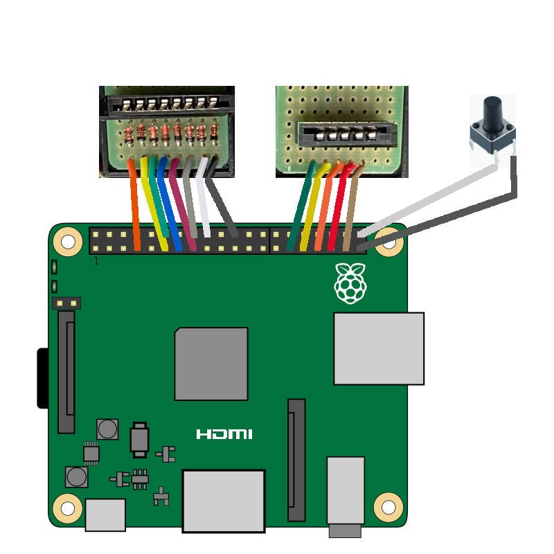
Next you need to connect the jumper wires to the GPIO and the mini PCBs as per MagPi 67 written by PJ Evans.
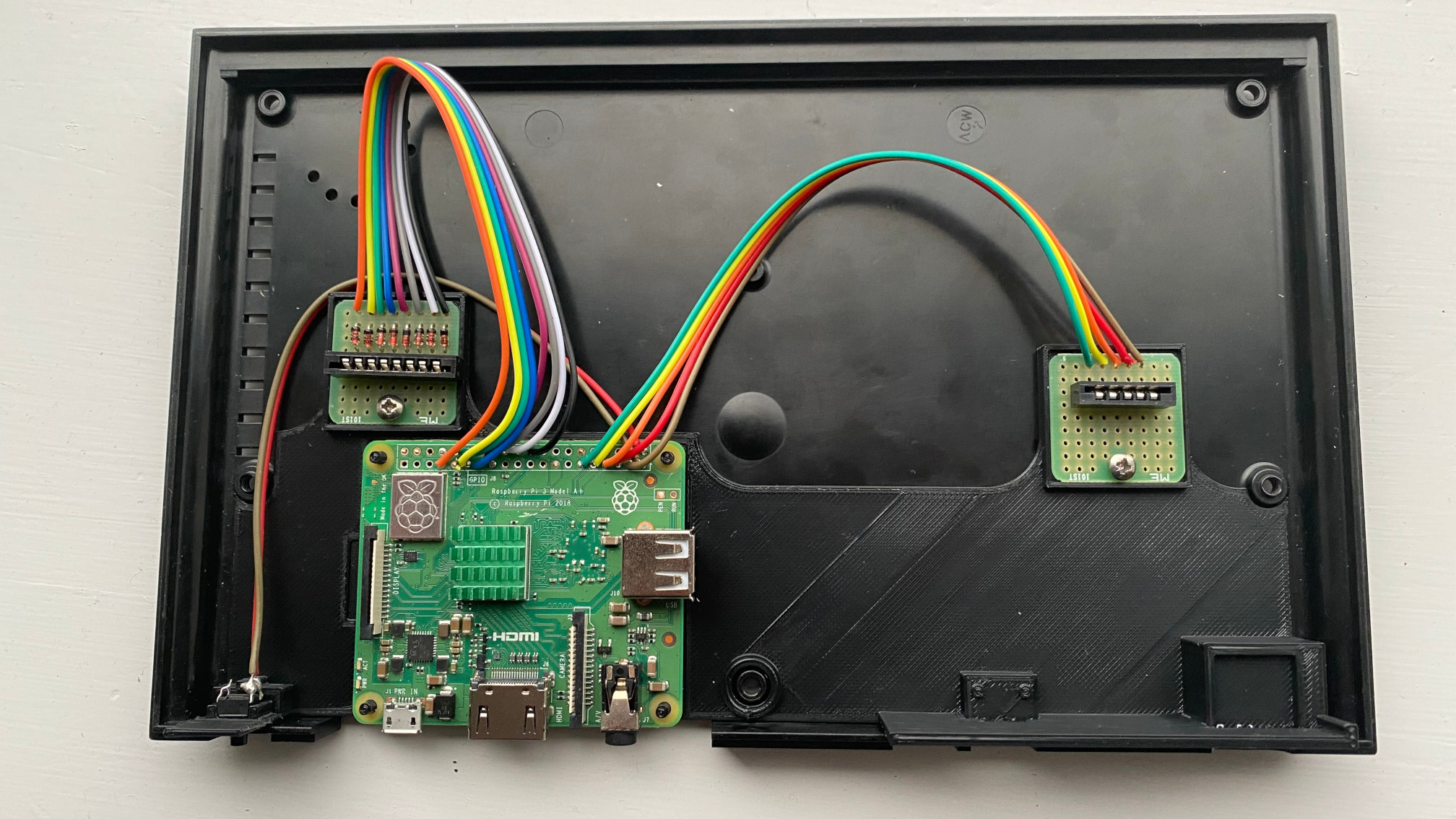
The diagrams below also show how this should be wired up. Please note the orientation of the membraine
connectors and the position/orientation of the diodes (black line).
I've simplified the first diagram to make it easier to read so please
note that the actual orientation is different if you use the inset to mount in the case (second diagram). The
key is to make sure the membraine connector metal pins are at the top for the LHS and bottom for the RHS (if looking with the back of
the case at the bottom).

Wiring Diagram (Click for Zoom) |

Final Wiring (Click for Zoom) |
The 3D printed backet has slots for both PCBs and the button and you can secure the PCBs with a small screw. The button
should just push on. In addition there is a cap which secures the Pi in place and helps with overal stability by fixing the
insert to the screw pillars.
If all you want to do is use this with ZXBaremulator and don't require the USB or SD Card extension then
you are ready hardware wise. All you need to do is download the latest version of ZXBaremulator from the website.
Pop it on a Micro SD Card and into the 3A+. Connect the keyboard membrane, reassemble the case and plug in the HDMI & Micro USB Power.
ZXBaremulator does not require the Keyboard polling software as it is built in.
The push button switches the keyboard to an alternate mode where the numbers are now function keys
so you can access the emulator menus.
.jpg)
With Securing Cap |
.jpg)
All Connected |
.jpg)
Backside |
Adding USB & SD Extension Ports
If you would like to use the Pi for other emulators or just want to add a joystick or swap out the SD card
then I recommend you use the second bracket which extends the ports of th Pi 3A+ to the back of the case.
To extend the USB the easiest way is to just cut a normal USB cable and wire this up to a micro USB PCB board. Hopefully
the USB cable has the correct colours which are Red for VCC, white for D-, green for D+ and Black for GND. The 3D printed insert
has a bracket for the PCB and it should just clip on securely. You can always add some glue if you are worried it will
come off.
For the Micro SD slot you need to either get a 25cm or a longer ribbon cable which you cut down to size. If you cut
a ribbon cable you will need to desolder and resolder the pins. I recommend you do this on the male connector (the one that plugs into the Pi) and not the socket as it is easier.
Once you cut the ribbon you will need to scrape the plastic away to expose the metals connectors ready for soldering. You will need to be
careful doing this as it easy to scrape away the metal as well. Also be mindful of orientation as per usual. After soldering wrap some insulating tape
around to ensure no short circuits.
Now you can connect everything up.
.jpg)
Added USB Port |
.jpg)
Added SD Card Port |
.jpg)
Additional Ports |
Using other Software with a Keyboard Scanner
If you want to use your new ZXPi Spectrum for other software (not ZXBaremulator) and want to use the keyboard you
will need to set-up a keyboard scanner. Details on how to set this up are on MagPi 67 or
via PJ Evan's github.
In addition you can also plug in a USB keyboard either via the extension (if you added one) or using a splitter
so the Micro USB on the back of the Pi has both power and the keyboard connected.