ZX Spectrum +3 & Amstrad CPC6128 Internal Floppy Emulator Project
After getting annoyed at the failure rate of my old 3.5" floppy disks I started using a Gotek USB
Floppy emulator on my Amiga and Atari ST. Being impressed with how well that worked I
decided to give it a shot on my trusty ZX Spectrum +3 who's disks are as equally unreliable,
even harder to source and also very expensive.
On my other Gotek drives I use the
FlashFloppy firmware (still in
active development at time of writing v0.9.27a - Aug'18)
and recent developments have included .DSK support for the Amstrad CPC & Spectrum +3
(basically the same format). Therefore as a test I mocked up some connectors (as described
here),
plugged it all in and got it running nicely with compatibility at 100% of the disks I've tested. A list of the TOSEC collection
tested disks can be found here. I've also written a small utility which removes the need to re-dump the
weak sector protected disks by adding this extra information to the eDSK automatically. You can download a Windows executable
here or follow the instructions detailed on the FlashFloppy wiki here.
I was impressed enough to decide to permanently replace the internal drives of a couple of
my machines, including creating a 3D printed drive caddy as the Gotek case won't fit in a 3" drive bay. Also as there
is no file-selector for the ZX Spectrum I added a rotary encoder with OLED display to navigate the files on the USB
stick, and topped it off with a sound buzzer to emulate the sound of the original drive.
Below is a guide on how I built all of this, heavily utilising the resources of the web, including the parts I used and
links to the 3D printed caddy I designed so you can print your own.
A lot of the information below is from the
FlashFloppy wiki
so I highly recommend you read that to get more information and more detailed schematics.
The Parts with links to eBay or Amazon (*other sellers are available)
USB Floppy Emulator Drive
Model used SFRC922D
PL2303HX USB TTL Adapter
Wires added with female pin connectors
I2C 0.91" 128x32 OLED Display Module
Best getting one with pins already added
KY-040 Rotary Encoder with Knob
Knob has 6mm D type socket
Passive Piezoelectric Buzzer
Floppy Molex Power Splitter
26way Ribbon Cable + IDC male Connector
Easiest to source with connectors already on
34way Female IDC Connector
Shown already made up but need to source loose
PCB Header Pin Strip
Get 40pin strip as easiest to source
Jumper Wires
Need 20cm long with F-F connectors
You will also need the following tools
The build
Flash the Gotek drive with the latest FlashFloppy firmware. Best way is to follow the guide on the
FlashFloppy wiki.
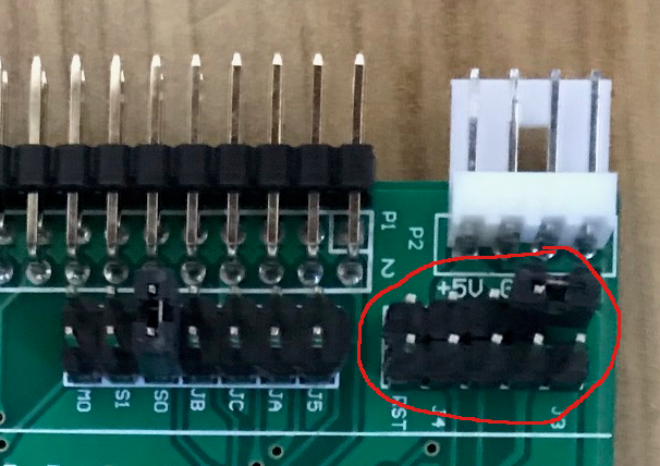
Once done make sure you remove the system-bootloader jumper and pop it somewhere safe.
Depending on the drive you get you may need to solder some pin headers to the board
as shown in the photos to the right.
|
|
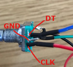
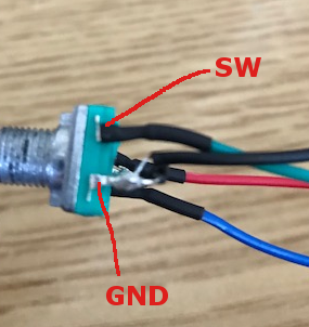
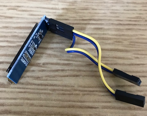
Wire up the rotary encoder. These usually come with a PCB which is not needed and is too large. De-solder the encoder and wire it up as per the photos and the FlashFloppy wiki. Note the two ground pins are linked on the encoder with a wire with a second wire run out for connection. I recommend the green & black wires are ~15cm long and the blue & red ~10cm.
|
|
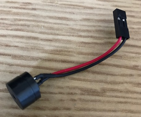
Solder two jumper wires to the 2 pin Piezoelectric buzzer so it can be connected straight to the GoTek board.
|
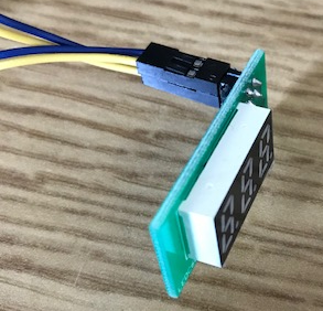
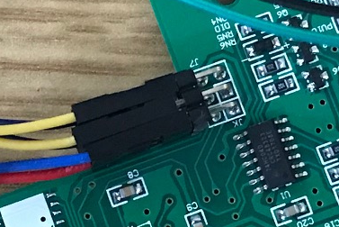
Wire up the OLED using the cables from the display that comes with the Gotek drive. You need to swap the cables around so instead of the two yellow wires on one side they are now top (pin1) and bottom (pin4) (see photos & FlashFloppy wiki). Your Gotek may have different coloured wires but basically just make sure the pins match up.
|
|
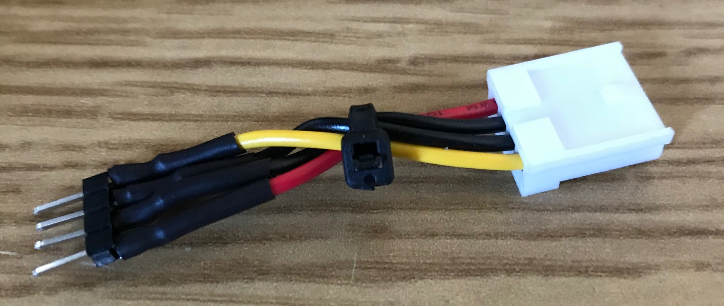
Take the Molex to floppy splitter and cut off one the floppy power connectors. Now solder a 4pin header to the bare wires (see photo). Note the twist in the wire due to the 3" drive having the +12V and +5V rails reversed. If you can source a 4pin male header then it would be better but I struggled to find these. Recommend this connector is ~6cm long
|
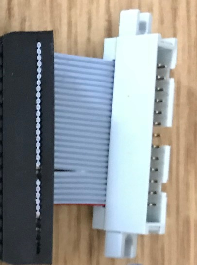
Make up the 26way to 34way floppy connector (as described on the CPC wiki). Take the 26way IDC male connector with ribbon cable and cut it about 5-6cm from the IDC. Then split the ribbon 6 wires from the red line and feed this into the 34way connector leaving a 2wire gap (see photo). Once you have this in position crimp the 34way shut (I use a vice)
|
Time to wire everything up as per the
FlashFloppy wiki.
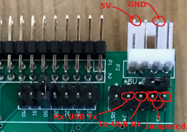
At the back of the Gotek board:
|
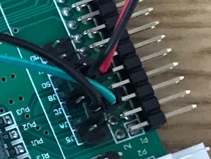
|
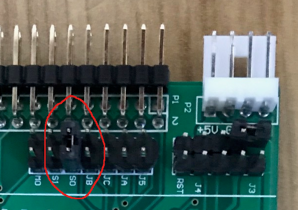
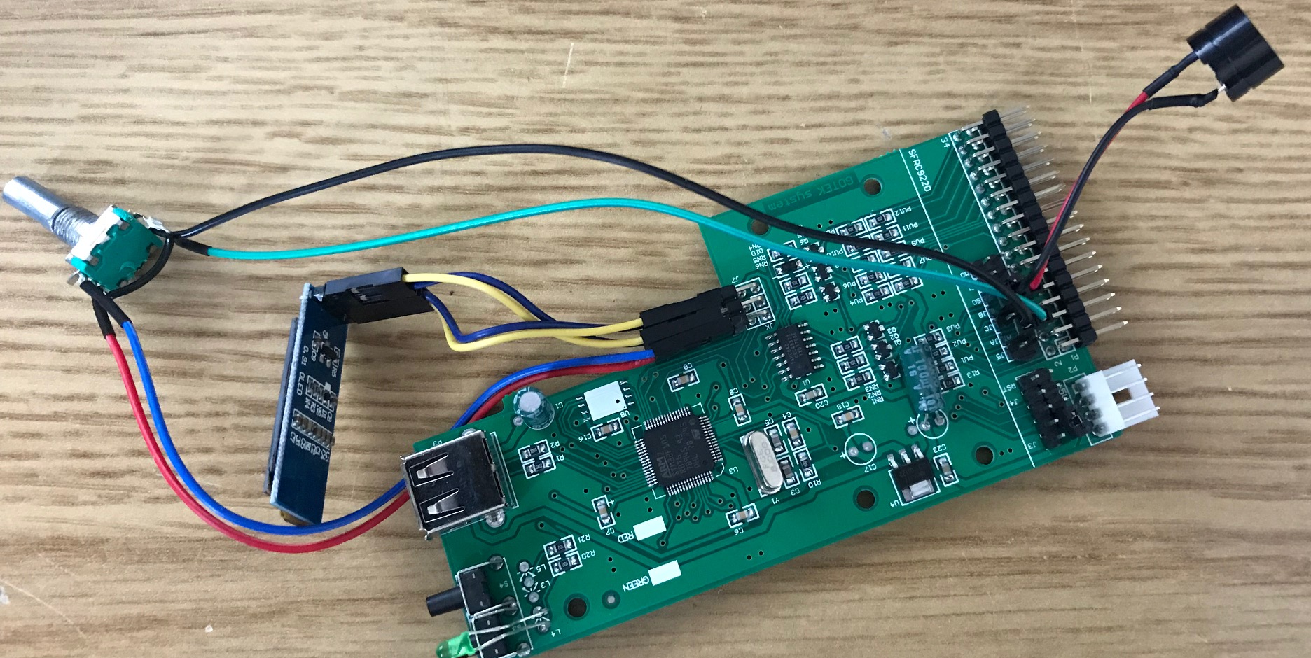
In the middle of the Gotek board are 6 more pins:
|
The photo on the right (click for hi-res version) shows the fully wired up drive (minus the power & floppy ribbon cable). Adding the power (be careful with the +5V and +12V, see photo) and ribbon connector you can now test this in your Spectrum or Amstrad to make sure it powers up and you see the FlashFloppy firmware version notification on the OLED.
|

|
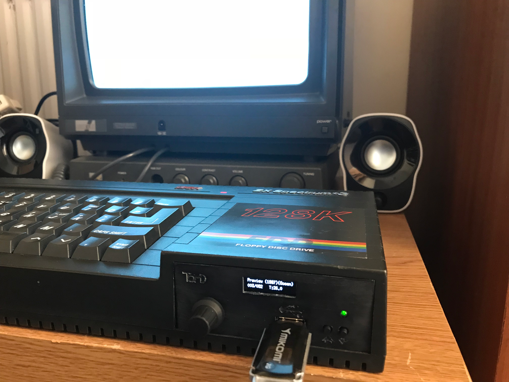
All that is missing now is a bracket to house the drive so it fits neatly into the Spectrum +3 or Amstrad CPC6128 (drives are the same size). You can find the bracket I've designed on Thingiverse. I designed it so that you can use the existing internal mounts and screws. You can see it mounted in an CPC6128 & Spectrum +3 in the photos (click for hires versions)

|
|
Now you are all set for loading up a USB stick with some .DSK files (get them on WoS or Google it)
and try them out. The USB stick needs to be
formatted FAT32 and you can use larger drives (16GB+) as long as they are formatted FAT32, however,
I recommend 2 or 4GB as this easily enough to fit every Spectrum and Amstrad disk on.
I also highly recommend you create sub-folders on the USB stick
(0-9, A...Z) to put the .DSK files in, to make it much easier to navigate.
Long filenames are supported which also helps with navigation and the display scrolls if they are longer
than it can show in one go.
You navigate the disk files using the Rotary Encoder, left turn to go up, right to go down. You push the knob in to select
a disk or eject one that is already in. You can also go to the top of a directory by pressing both of the buttons
on the right of the Gotek drive. This helps go back up a directory without have to scroll through all the disks.
Once a disk is selected it behaves exactly like a real 3" disk would (no NMI buttons).
You can therefore use the standard
Loader on the Spectrum +3 menu or go into +3 basic and type cat etc... For the Amstrad it is the same with the
standard Load"Disc" or |CPM working as they should.
I do recommend tweaking the FlashFloppy
config file to help with navigation
and disk selection. I usually turn off automatic disk and folder selection and use rotary-fast so that the GoTek buttons navigate faster.
Have fun... Tom