GBS-8200 RGB-VGA 1080p Upscaler for Retro Computer/Consoles
This project initially started life as a way of getting the Monitor 80 column mode of my Sinclair QL working on a modern display. It eventually transformed into a way of connecting nearly all of my retro computers and consoles to my 1080p monitor with a lovely crystal clear display. I now use this to upscale all my retro machines with the only real downside being that it doesn't cover the retro machines that only have composite or RF out, but you can't have everything.
Having owned a couple of Sinclair QLs for a while I've always wanted to try the 80 coloumn Monitor mode but never had a
suitable monitor. I've used the easily available SCART cable to connect it to my LCD TV, which works great, but when selecting Monitor mode it cuts off the sides of the screen so is unusable. I read on the QL forum that the reason for this is that the QL is expecting a non-standard fast beam return monitor and therefore just won't work with modern screens.
Luckily also on the same forum a solution was presented to use an upscaler which buffers the screen output and can therefore get around the non-standard nature of the output. One low-cost solution discussed on the forum was to use a GBS-8200 RGB-VGA converter which are most often coupled with old arcade boards to get them to display on VGA monitors. So I purchased one to experiment with...
GBS-8200 Board
eBay Link
The GBS-8200 is a low cost (~£15) 24-bit A/D RGB-VGA converter used to convert such things as
15KHz CGA for use with modern displays. It has sockets for component YUV, VGA, on-board headers for RGBS & RGBHV and
requires a 5-12V power input.
From the factory it outputs VGA at either 640x480, 800x600, 1024x768 or 1360x768
and has controls to position and resize the image. The output is also
at 60Hz NTSC which, although not ideal, shouldn't be an issue for modern displays.
For use with the QL (and others) I've used the RGBS input via the 8pin onboard JST header -> (R)ed (G)reen (B)lue + (S)ync
Initial Set-Up of the GBS-8200 Board
I purchased a v4.0 board from eBay as I read it has the least issues (v5.0 & the dual VGA output 8220s have an
LDO oscillation problem)
and also seemed to be the easiest to get hold of.
The board came with two connectors, one for the 8pin RGBS header and the other for the power input.
As it came with the appropriate connector I decided to use it to get the QL output into the GBS-8200
and also to power the board via USB to save me having to dig out a 5V PSU with a jack output.
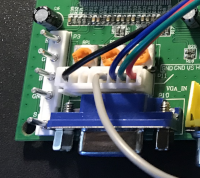
8-Pin RGBS Connector |
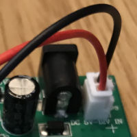
Alt Power Input |
For power I initially used a 5V power adapter with jack plug but eventually opted for USB as it was easier. To create a USB power wire I simply cut one end off a USB cable keeping the type A end. I then jut soldered the red & black wires from the supplied cable to the appropriate wires from the USB cable with a bit of heat shrink for protection. This gave me a cheap and reliable power source. The board doesn't draw much power (only 0.4A) so an iPhone charger seems to work fine. I'd recommend a good 2A charger though, especially if you use some of the add-on boards discussed later, avoid the cheap Chinese ones.
The supplied 8-pin JST connector comes with connections for RGB plus H & V Sync (gray & yellow wires respectively). Although the QL does supply a V-Sync output I've not used it as a little experimenting showed it made no difference to the eventual output, others may have more mileage with this. I therefore removed it from the socket leaving Ground, Red, Green, Blue & Sync (using the H-Sync gray wire input)
I left the rest of the board as-supplied
Connecting to the QL
My first attempt of connecting the QL to the board was simply to connect an 8pin DIN to the other end of the JST connector, wiring the RGB & S to the appropriate pins as defined by the SCART cable connector. Composite sync went to the gray Sync cable and I kept the resistors as per the diagram (330Ω on the Sync & 390Ω on the RGB signals)
Powering up I was pleased to see that without changing anything I got a display at 640x480 and although it was not 100% stable (occasional flickering/loss of sync) and the colours were very washed out I was pleasantly surprised. I replaced the RGB resistors with 68Ω and the colours looked a little better and also replaced the sync resistor with 1KΩ to get the image to be stable at all resolutions. Monitor mode worked as well after some tweaking of the H & V scaling to get it all to fit.
I changed the 8pin DIN for a 6pin DIN socket so i could also try the GBS-8200 with my BBC Micro (Model B), building an 8pin to 6pin DIN adapter for the QL. The BBC Micro also worked well although I did have to add a 330Ω to the sync line to get the image to be stable (and 68Ω to the RGB lines). The images below show the output of the QL & BBC Micro experiments (click for hi-res version)
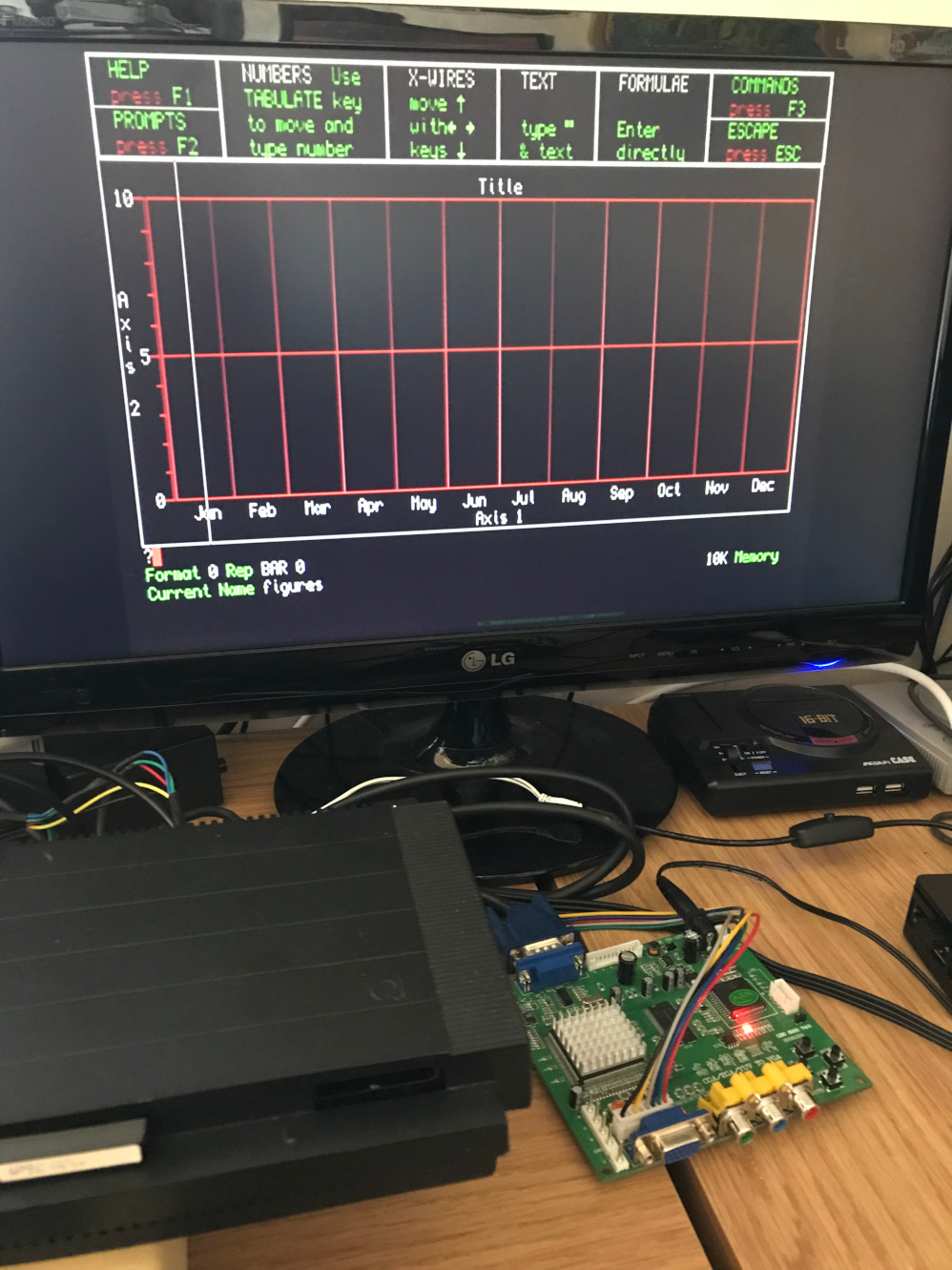
QL Monitor Mode |
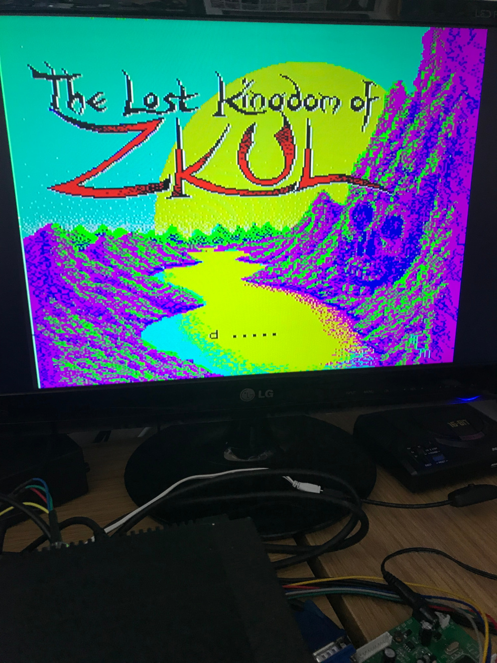
QL TV Mode |
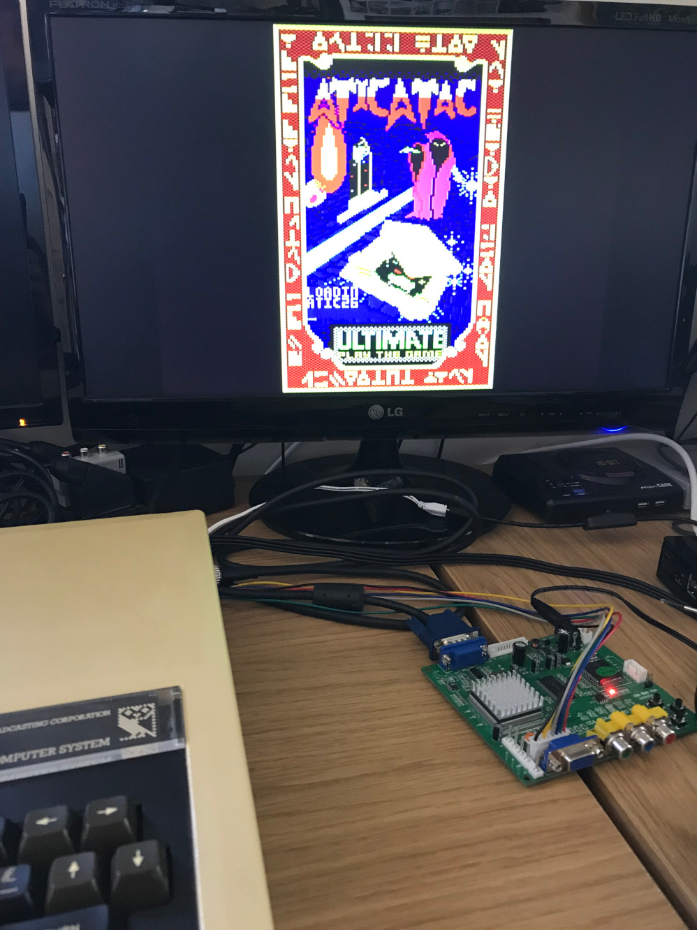
BBC Micro |
The Sync-Splitter
Further reading of the Forums I saw a few mentions of building a simple Sync Splitter circuit to improve image stability as the circuit would clean up the sync output. It would also allow the GBS-8200 to be used with more retro computers and consoles in particular those that don't have dedicated composite sync output (just a composite video out).
The circuit in question used the LM1881N Video Sync Separator chip. I built the reference circuit as described in the technical specs and connected the GBS-8200 sync line to pin 1 and the output from the QL/BBC to pin 2.
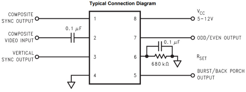
LM1881N Reference Circuit |
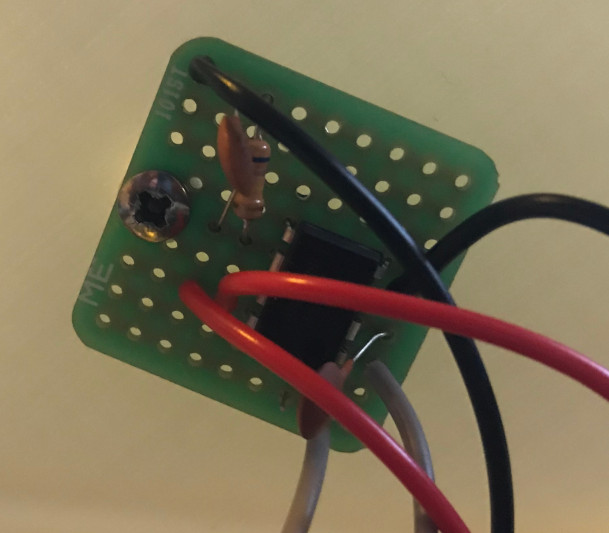
My LM1881N Circuit |
In order to fully test this new circuit I adapted the 6pin DIN input so that it now connected to a SCART female socket allowing me to use this with and test multiple machines, including the QL, via the many SCART cables I had already purchased. I figured that the shop bought SCART cables already contained the correct resistors and extra circuitry needed to get the RGB & S signals to the correct levels saving me having to build multiple custom cables. In addition I could extract the audio and some of the connectors for the retro machines are difficult to source such as the one for the Atari ST and Sega Saturn.
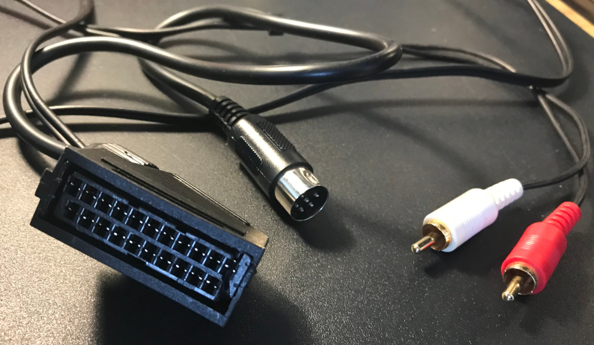
SCART Lead to 6pin DIN with Audio Breakout |
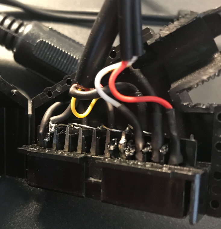
SCART Lead Inside |
Initially I saw very little difference in the output and in fact found the image to be strangely less stable than before, although I was now able to use the GBS-8200 with other retro machines such as the Sinclair ZX Spectrum 128k which has dedicated circuitry in the SCART cable to add a bright signal to the RGB output. A little more investigating pointed me towards adding a 75Ω resistor from the input pin to ground and a 470Ω resistor between the Sync output (pin 1) and the GBS-8200 board, and this really improved stability. The following diagram shows my v1 circuit.
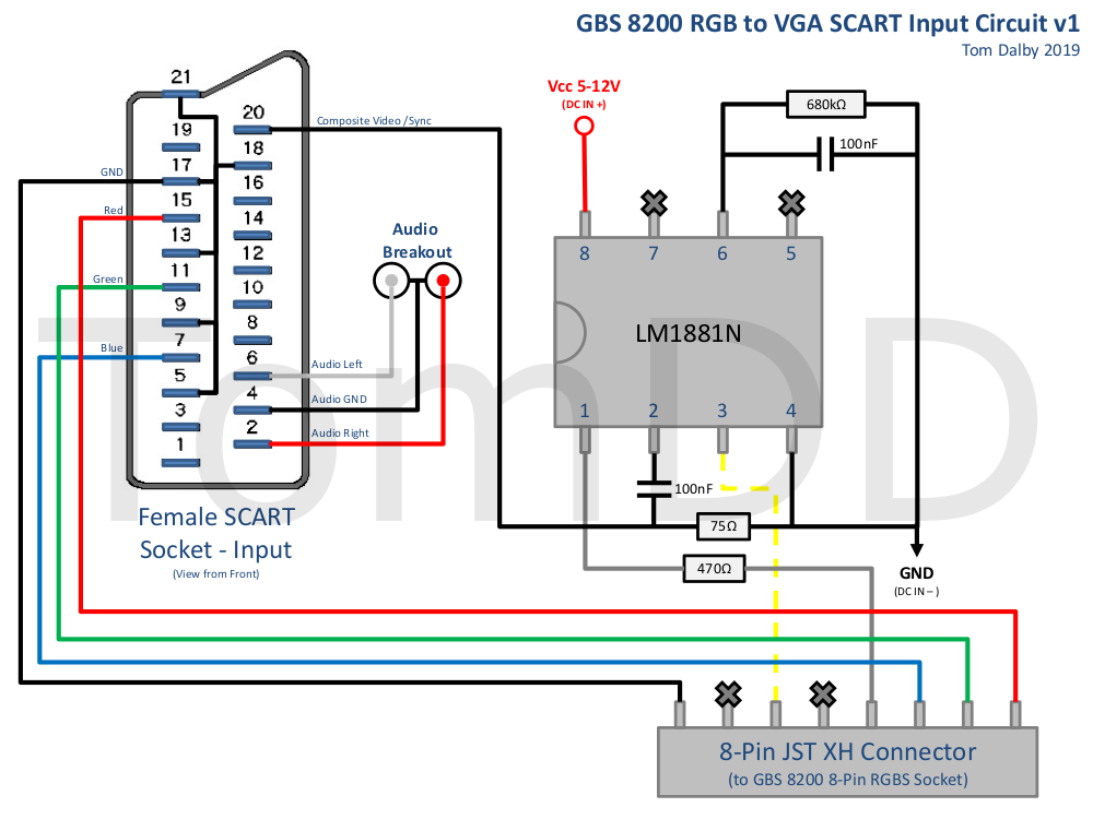
GBS-8200 SCART Circuit v1 |
I further refined the design by removing the Rset circuit as this was only used for the V-Sync output, which I don't use, and also adding a 100nF power bypass capacitor as discussed here and here. The only other change I made was to twist the three pots above the RGBS connector as far to left as they would go to get the best brightest RGB colours. Below is my final v2 circuit.
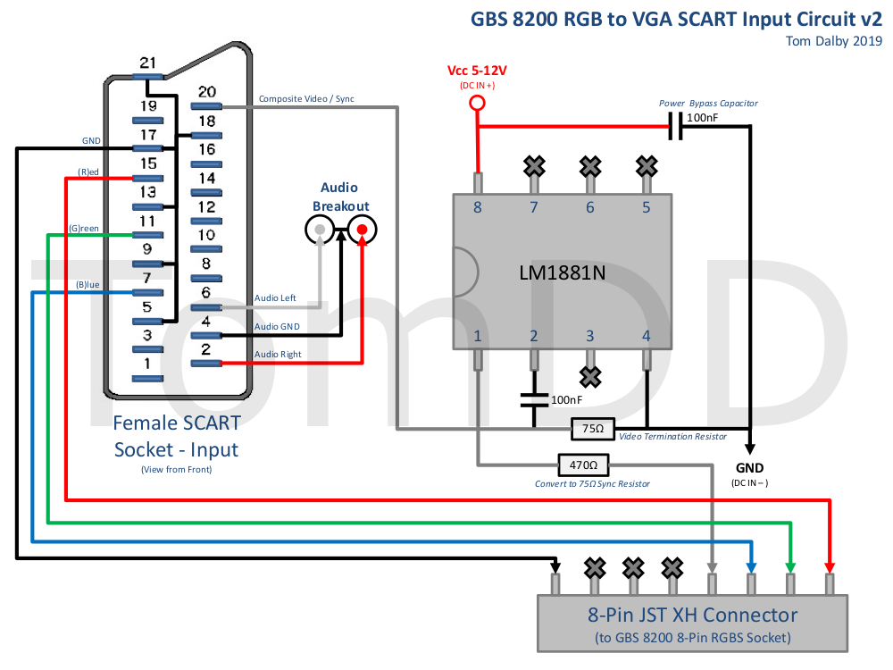
GBS-8200 SCART Circuit v2 |
I read a few people in the forums complaining that the quality of the GBS-8200 boards vary a lot so I bought a 2nd v4.0 board to see if it was any different and I'm pleased to report that the output was exactly the same as my original. Finally I built a custom case to house the board, you can find the design on Thingiverse
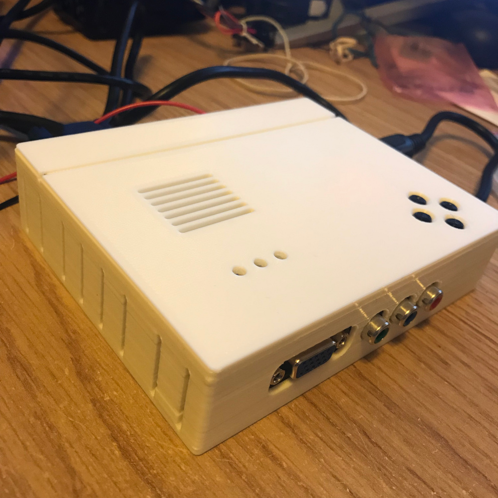
GBS-8200 with Case |
Custom Firmware (gbs-control)
Although happy with the v2 design the output is far from perfect. The 50Hz output from all my PAL machines is being shown at 60Hz which creates some minor stuttering (very difficult to notice to be honest) and the maximum resolution of the board is 1366x768 which isn't very crisp on modern displays which are most likely 1080p or above.
While experimenting above I came across the CFW project gbs-control by ramapcsx2. I had heard very good things about it especially if using PAL machines so using my 2nd GBS-8200 board I purchased the extra components as detailed on the wiki set-up guide.
I went with a NodeMCU v3 ESP8266 board which I got on eBay and initially just wired the board up by adding a header to the p5 plug on the GBS-8200 board and adding a wire to the Debug pin of IC6 as shown in the wiki and this photo.
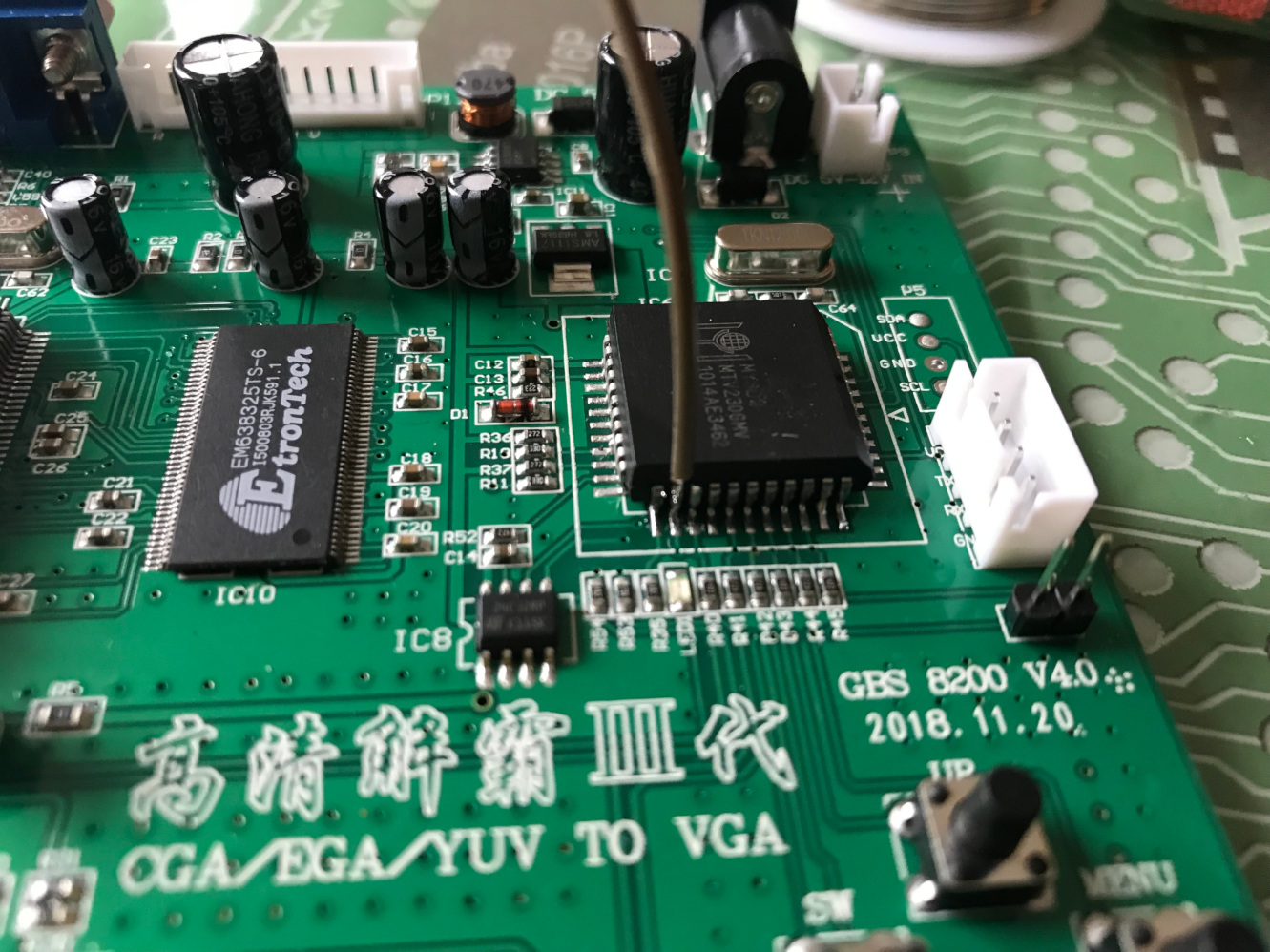
GBS-8200 CFW Debug Pin |
I downloaded the Arduino IDE v1.9.0beta, the latest version of gbs-control and flashed the NodeMCU as per the instructions on the wiki. I also set-up the wifi and connected it all up to the GBS-8220. Upon powering up I was amazed at how clear the picture was and with a little tweaking via the web interface (http://gbscontrol.local/) I was able to get a crystal clear 1080p image on my monitor on all the systems I tested including Amstrad CPC, ZX Spectrum 128k, +2 & +3, BBC Micro & Sinclair QL.
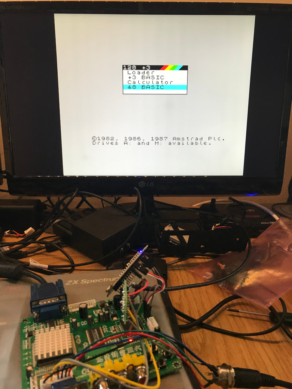
GBS-8200 CFW Setup with ZX Spectrum +3 RGB Out |
The following pictures show comparisons between the normal GBS-8200 (top) & the CFW at 1080p (bottom).
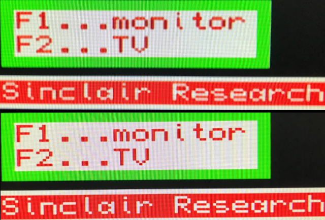
Normal vs. CFW - Sinclair QL |
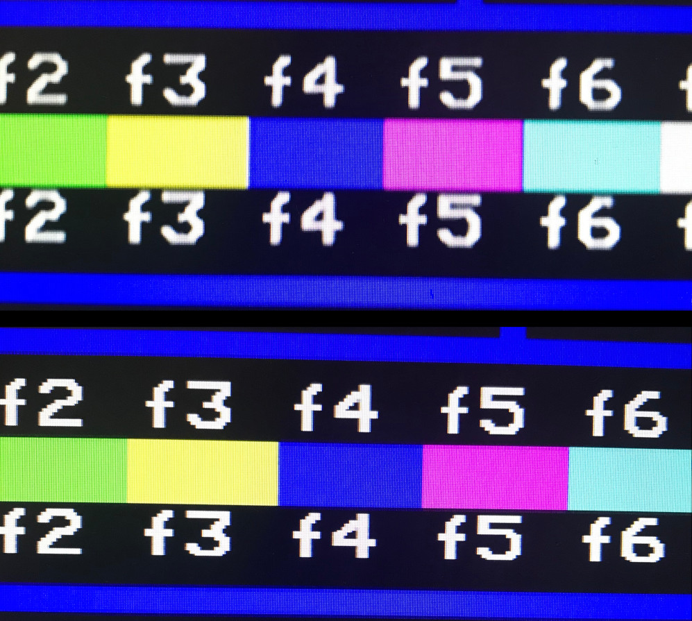
Normal vs. CFW - BBC Micro |
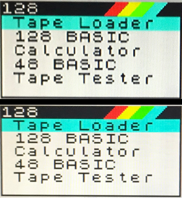
Normal vs. CFW - ZX Spectrum 128k |
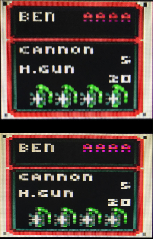
Normal vs. CFW - Amstrad CPC6128 |
To make the CFW permanent I adapted the circuit using a 44pin chip socket mounted on a piece of PCB prototype board so I didn't need to have a flimsy wire on the debug pin. I also used this board to mount the sync-splitter circuit so it wasn't floating about in the case. Finally I added a small switch so I could disable the CFW if needed by cutting the power to the NodeMCU daughter board and also opening the jumper on the GBS-8200 which is normally closed to enable the CFW.
Again a lot of the details are on the gbs-control wiki and some pictures of my circuit are below.
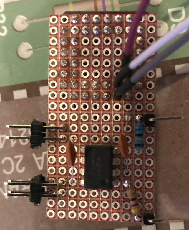
GBS-8200 CFW Chip Mount Circuit |

GBS-8200 CFW Full Setup |
As per the standard set-up I've also made a custom case to mount this all in, you can download it from Thingiverse. I also tried the smaller WEMOS D1 Mini instead of the NodeMCU and found it worked exactly the same but obviously a lot smaller which may suite some builds/cases better.
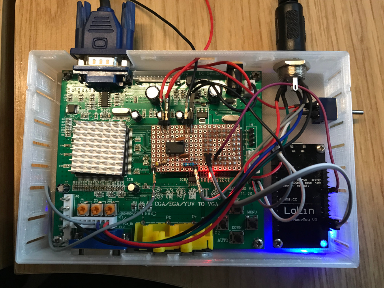
GBS-8200 CFW Full Setup in Case |
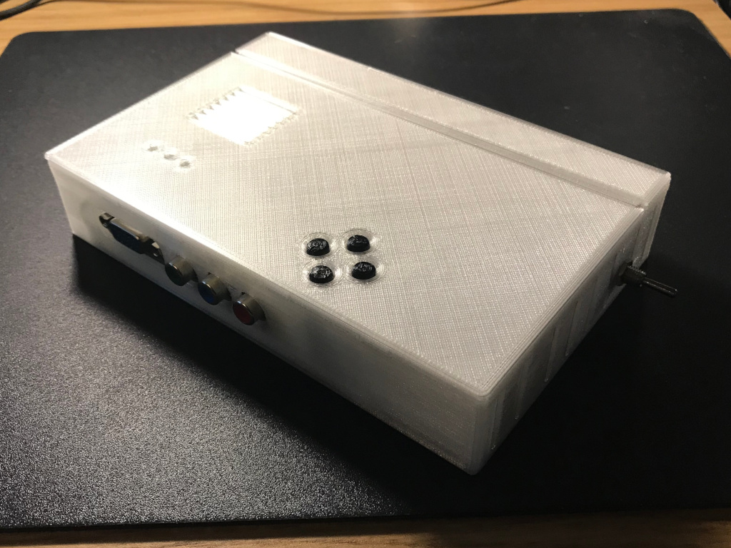
GBS-8200 CFW Case |
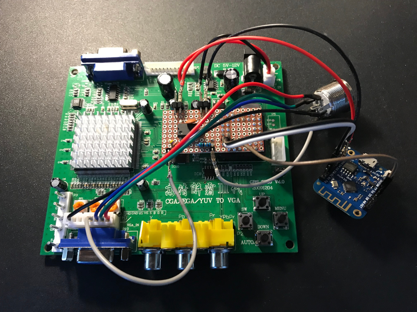
GBS-8200 CFW Setup with WEMOS D1 Mini |
Final Thoughts
Update June 2019: The latest version of the custom firmware has resolved all of the issues below with cropping & timings.
Although the output is very good from the CFW adapted GBS-8200 and I will use it daily for nearly all my retro machines, it does have one draw back. I originally set out to get the Monitor mode working for the Sinclair QL. The base GBS-8200 works fine for this, however, with the CFW installed the output is unfortunately slightly cropped on the right hand side. No amount of tweaking the settings has fixed this for me, although I will explore other options such as adjusting the Arduino code. As such to get full Monitor mode I have to disable the CFW, hence why I added the switch detailed above. The picture below shows the comparison between the two versions, with the CFW at the bottom.

GBS-8200 CFW vs. Normal - Sinclair QL Monitor Mode |
Small update (13/4/19). It seems the cropping can be easily fixed by adjusting the timings. The author of the custom firmware gave me a command which, once entered into the NodeMCU via the Arduino Serial Monitor, adjusts the screen to fit perfectly (still requires some tweaking via the Picture Manager). The command is s5s12s7fjn zzzzz